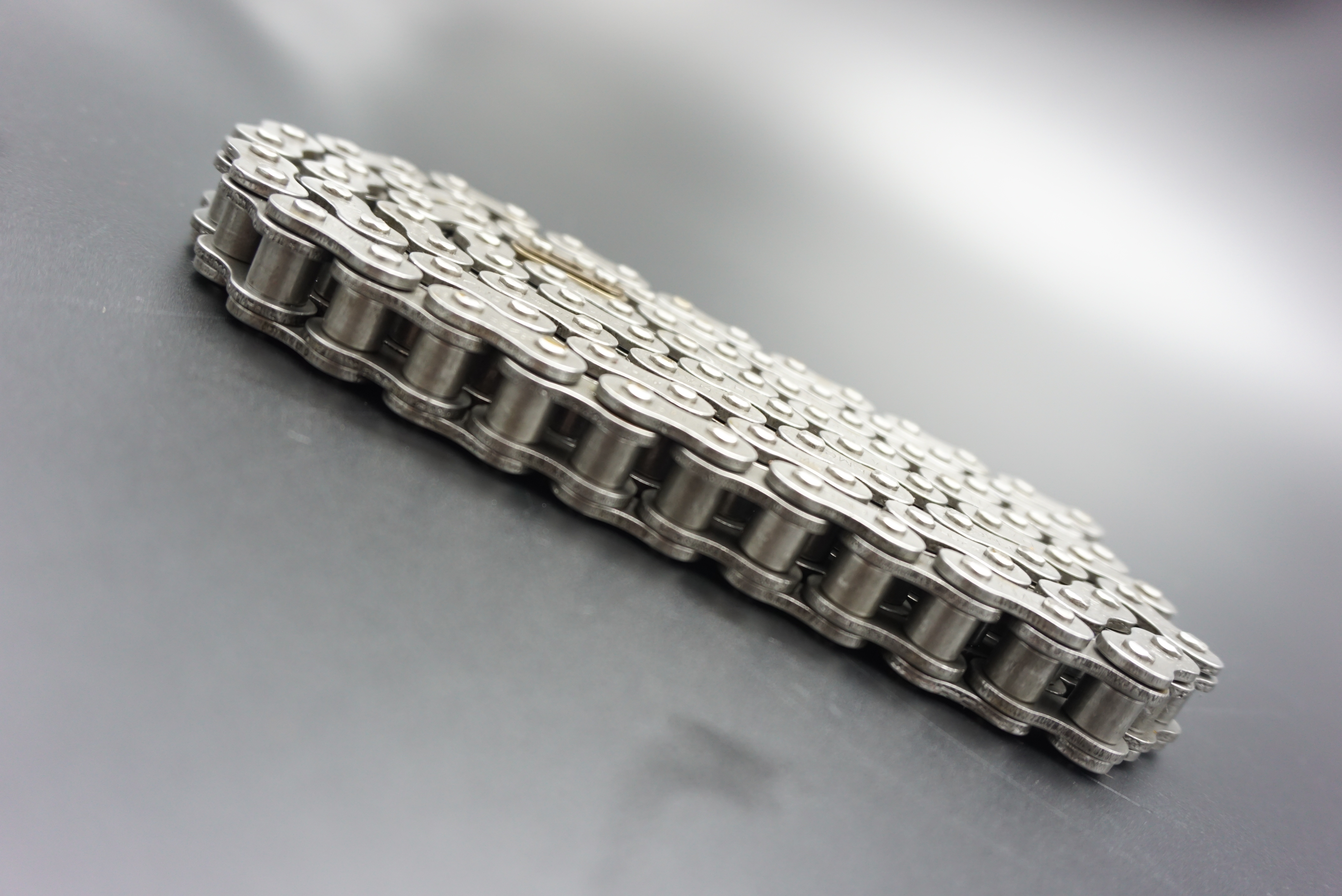
Roller Chain Outer Link Plate Stamping Process Standards
In industrial transmission systems, roller chains are core transmission components, and their performance directly determines the equipment’s operating efficiency and service life. The outer link plates, the “skeleton” of the roller chain, play a crucial role in transmitting loads and connecting chain links. The standardization and precision of their manufacturing process are crucial factors affecting the overall quality of the roller chain. Stamping, the mainstream method for manufacturing outer link plates, requires strict standards at every step, from raw material selection to finished product delivery, to ensure the outer link plates possess sufficient strength, toughness, and dimensional accuracy. This article will provide an in-depth analysis of the full process standards for roller chain outer link plate stamping, providing industry practitioners with a professional reference and allowing end users to more clearly understand the process logic behind high-quality roller chains.
I. Basic Assurances Before Stamping: Raw Material Selection and Pretreatment Standards
The performance of outer link plates begins with high-quality raw materials. The stamping process sets clear requirements for the material’s mechanical properties and chemical composition, which are prerequisites for the smooth execution of subsequent processes. Currently, the mainstream materials for outer link plates in the industry are low-carbon alloy structural steels (such as 20Mn2 and 20CrMnTi) and high-quality carbon structural steels (such as 45 steel). The choice of material depends on the roller chain’s application (e.g., heavy loads, high speeds, and corrosive environments). However, regardless of the material chosen, it must meet the following core standards:
1. Raw Material Chemical Composition Standards
Carbon (C) Content Control: For 45 steel, the carbon content must be between 0.42% and 0.50%. A higher carbon content can increase the material’s brittleness and cracking during stamping, while a lower carbon content can affect its strength after subsequent heat treatment. The manganese (Mn) content of 20Mn2 steel must be maintained between 1.40% and 1.80% to improve the material’s hardenability and toughness, ensuring that the outer link plates resist fracture under impact loads. Harmful Element Limits: Sulfur (S) and phosphorus (P) content must be strictly controlled below 0.035%. These two elements can form low-melting-point compounds, causing the material to become “hot brittle” or “cold brittle” during the stamping process, impacting the yield of finished products.
2. Raw Material Pretreatment Standards
Prior to entering the stamping process, raw materials undergo three pretreatment steps: pickling, phosphating, and oiling. Each step has clear quality requirements:
Pickling: Using a 15%-20% hydrochloric acid solution, soak at room temperature for 15-20 minutes to remove scale and rust from the steel surface. After pickling, the steel surface must be free of visible scale and free of excessive corrosion (pitting), which can affect the adhesion of the subsequent phosphate coating.
Phosphating: Using a zinc-based phosphating solution, treat at 50-60°C for 10-15 minutes to form a phosphate coating with a thickness of 5-8μm. The phosphate coating must be uniform and dense, with adhesion reaching Level 1 (no peeling) using the cross-cut test. This reduces friction between the stamping die and the steel plate, extending die life and enhancing the rust resistance of the outer link plate.
Oil application: Spray a thin layer of anti-rust oil (thickness ≤ 3μm) onto the phosphate coating surface. The oil film should be evenly applied without any gaps or accumulation. This prevents rusting of the steel plate during storage while maintaining the accuracy of subsequent stamping operations.
II. Standards for Core Stamping Processes: Precision Control from Blanking to Forming
The stamping process for roller chain outer links primarily consists of four core steps: blanking, punching, forming, and trimming. The equipment parameters, die accuracy, and operating procedures of each step directly impact the dimensional accuracy and mechanical properties of the outer links. The following standards must be strictly adhered to:
1. Blanking Process Standards
Blanking involves punching raw steel sheets into blanks that conform to the unfolded dimensions of the outer links. Ensuring the dimensional accuracy and edge quality of the blanks is crucial for this process.
Equipment Selection: A closed single-point press is required (tonnage varies depending on the outer link size, generally 63-160kN). The press’s slide stroke accuracy must be controlled within ±0.02mm to ensure consistent stroke for each press and avoid dimensional deviation.
Die Accuracy: The clearance between the punch and die of the blanking die should be determined based on the material thickness, generally 5%-8% of the material thickness (e.g., for a 3mm material thickness, the clearance is 0.15-0.24mm). The roughness of the die cutting edge must be below Ra0.8μm. Edge wear exceeding 0.1mm requires prompt regrinding to prevent burrs from forming on the blank edge (burr height ≤ 0.05mm).
Dimensional requirements: The blank length deviation must be controlled within ±0.03mm, the width deviation within ±0.02mm, and the diagonal deviation within 0.04mm after blanking to ensure accurate datums for subsequent processing steps.
2. Punching Process Standards
Punching is the process of punching the bolt holes and roller holes for the outer link plates into the blank after blanking. The hole position accuracy and diameter accuracy directly impact the assembly performance of the roller chain.
Positioning Method: Dual datum positioning (using two adjacent edges of the blank as the reference) is used. The locating pins must meet IT6 accuracy to ensure consistent blank position during each punching. The hole position deviation must be ≤ 0.02mm (relative to the outer link plate reference surface). Hole Diameter Accuracy: The diameter deviation between the bolt and roller holes must meet IT9 tolerance requirements (e.g., for a 10mm hole, the deviation is +0.036mm/-0mm). Hole roundness tolerance should be ≤0.01mm, and hole wall roughness should be below Ra1.6μm. This prevents chain links from being too loose or too tight due to hole diameter deviation, which could affect transmission stability.
Punching Order: Punch the bolt holes first, followed by the roller holes. The center-to-center distance deviation between the two holes must be within ±0.02mm. Cumulative center-to-center distance deviation will directly lead to pitch deviation in the roller chain, which in turn affects transmission accuracy.
3. Forming Process Standards
Forming involves pressing the punched blank through a die into the final outer link plate shape (e.g., curved or stepped). This process requires ensuring the outer link plate’s shape accuracy and springback control.
Mold Design: The forming die should adopt a segmented structure, with two stations, pre-forming and final forming, configured according to the outer link plate’s shape. The pre-forming station initially presses the blank into a preliminary shape to reduce deformation stress during final forming. The final forming die cavity surface roughness must achieve Ra0.8μm to ensure a smooth, indentation-free outer link plate surface.
Pressure Control: The forming pressure should be calculated based on the material’s yield strength and is generally 1.2-1.5 times the material’s yield strength (e.g., the yield strength of 20Mn2 steel is 345MPa; the forming pressure should be controlled between 414-517MPa). Too little pressure will result in incomplete forming, while too much pressure will cause excessive plastic deformation, affecting subsequent heat treatment performance. Springback Control: After forming, the springback of the outer link plate must be controlled within 0.5°. This can be counteracted by setting a compensation angle in the mold cavity (determined based on the material’s springback characteristics, generally 0.3°-0.5°) to ensure that the finished product meets the design requirements.
4. Trimming Process Standards
Trimming is the process of removing flash and excess material generated during the forming process to ensure the edges of the outer link plate are straight.
Trimming Die Accuracy: The gap between the punch and die of the trimming die must be controlled within 0.01-0.02mm, and the cutting edge sharpness must be below Ra0.4μm. Ensure that the edges of the outer link plate after trimming are burr-free (burr height ≤ 0.03mm) and the edge straightness error is ≤ 0.02mm/m.
Trimming Sequence: Trim the long edges first, then the short edges. This prevents deformation of the outer link plate due to improper trimming sequence. After trimming, the outer link plate must undergo a visual inspection to ensure that no defects such as chipped corners or cracks are present.
III. Post-Stamping Quality Inspection Standards: Comprehensive Control of Finished Product Performance
After stamping, the outer link plates undergo three rigorous quality inspection processes: dimensional inspection, mechanical property inspection, and appearance inspection. Only products that meet all standards can proceed to the subsequent heat treatment and assembly processes. Specific inspection standards are as follows:
1. Dimensional Inspection Standards
Dimensional inspection utilizes a three-dimensional coordinate measuring machine (accuracy ≤ 0.001mm) combined with specialized gauges, focusing on the following key dimensions:
Pitch: The outer link plate pitch (the distance between the two bolt holes) must have a tolerance of ±0.02mm, with a cumulative pitch error of ≤0.05mm per 10 pieces. Excessive pitch deviation can cause vibration and noise during roller chain transmission.
Thickness: The outer link plate thickness deviation must meet IT10 tolerance requirements (e.g., for a 3mm thickness, the deviation is +0.12mm/-0mm). Thickness variations within a batch must be ≤0.05mm to prevent uneven load on the chain links due to uneven thickness. Hole Position Tolerance: The positional deviation between the bolt hole and the roller hole must be ≤0.02mm, and the hole coaxiality error must be ≤0.01mm. Ensure that the clearance with the pin and roller meets the design requirements (the clearance is generally 0.01-0.03mm).
2. Mechanical Property Testing Standards
Mechanical property testing requires randomly selecting 3-5 samples from each batch of products for tensile strength, hardness, and bend testing.
Tensile Strength: Tested using a universal material testing machine, the tensile strength of the outer link plate must be ≥600MPa (after heat treatment of 45 steel) or ≥800MPa (after heat treatment of 20Mn2). The fracture must occur in the outer link plate’s non-hole area. Failure near the hole indicates stress concentration during the punching process, and the die parameters must be adjusted. Hardness Test: Use a Rockwell hardness tester to measure the surface hardness of the outer link plates. The hardness must be controlled within HRB80-90 (annealed state) or HRC35-40 (quenched and tempered state). Excessively high hardness will increase the material’s brittleness and susceptibility to breakage; excessively low hardness will affect wear resistance.
Bending Test: Bend the outer link plates 90° along their length. No cracks or breaks should appear on the surface after bending. The springback after unloading should be ≤5°. This ensures that the outer link plates have sufficient toughness to withstand the impact loads during transmission.
3. Appearance Inspection Standards
Appearance inspection utilizes a combination of visual inspection and magnifying glass inspection (10x magnification). Specific requirements are as follows:
Surface Quality: The outer link plate surface must be smooth and flat, free of scratches (depth ≤ 0.02mm), indentations, or other defects. The phosphate coating must be uniform and free of missing coating, yellowing, or flaking. Edge Quality: The edges must be free of burrs (height ≤ 0.03mm), chipping (chipping size ≤ 0.1mm), cracks, or other defects. Minor burrs must be removed through passivation (immersion in a passivation solution for 5-10 minutes) to prevent scratches on the operator or other components during assembly.
Hole Wall Quality: The hole wall must be smooth, free of steps, scratches, deformation, or other defects. When inspected with a go/no-go gauge, the go gauge must pass smoothly, while the no-go gauge must not pass, ensuring that the hole meets assembly accuracy requirements.
IV. Stamping Process Optimization Directions: From Standardization to Intelligence
With the continuous advancement of industrial manufacturing technology, the standards for roller chain outer link stamping processes are also being continuously upgraded. Future development will be oriented toward intelligent, green, and high-precision processes. Specific optimization directions are as follows:
1. Application of Intelligent Production Equipment
Introducing CNC stamping machines and industrial robots to achieve automated and intelligent control of the stamping process:
CNC stamping machines: Equipped with a high-precision servo system, they enable real-time adjustment of parameters such as stamping pressure and stroke speed, with a control accuracy of ±0.001mm. They also feature self-diagnosis capabilities, enabling timely detection of problems such as die wear and material anomalies, reducing the number of defective products.
Industrial robots: Used in raw material loading, stamping part transfer, and finished product sorting, they replace manual operations. This not only improves production efficiency (enabling 24-hour continuous production), but also eliminates dimensional deviations caused by manual operation, ensuring consistent product quality.
2. Promotion of Green Processes
Reducing energy consumption and environmental pollution while meeting process standards:
Mold material optimization: Using a composite mold made of high-speed steel (HSS) and cemented carbide (WC) increases mold life (service life can be extended by 3-5 times), reduces mold replacement frequency, and reduces material waste.
Pretreatment process improvements: Promoting phosphorus-free phosphating technology and using environmentally friendly phosphating solutions reduces phosphorus pollution. Furthermore, electrostatic spraying of rust-proof oil improves rust-proof oil utilization (utilization rate can be increased to over 95%) and reduces oil mist emissions.
3. Upgrading High-Precision Inspection Technology
A machine vision inspection system was introduced to enable rapid and accurate quality inspection of outer link plates.
Equipped with a high-definition camera (resolution ≥ 20 megapixels) and image processing software, the machine vision inspection system can simultaneously inspect outer link plates for dimensional accuracy, appearance defects, hole position deviation, and other parameters. The system boasts an inspection speed of 100 pieces per minute, achieving over 10 times the accuracy of manual inspection. It also enables real-time storage and analysis of inspection data, providing data support for process optimization.
Conclusion: Standards are the lifeline of quality, and details determine transmission reliability.
The stamping process for roller chain outer link plates may seem simple, but strict standards must be adhered to at every stage—from controlling the chemical composition of the raw materials, to ensuring dimensional accuracy during the stamping process, to comprehensive quality inspection of the finished product. Oversight of any detail can lead to degradation of the outer link plate’s performance, and consequently, impact the transmission reliability of the entire roller chain.
Post time: Sep-26-2025