
Roller Chain Failure Analysis: Reading Broken Links
A roller chain never fails without leaving a record. The broken link, the worn pin, the cracked plate and the elongated pitch each describe the load history that destroyed the assembly. For a maintenance engineer, a plant buyer or a distributor handling a warranty claim, the job is forensic: read the surface, measure the loss, and decide whether the chain reached the end of its service life or whether an avoidable fault cut it short. This field guide maps the physical evidence to its root cause so the responsible party can be identified before the next chain is ordered.
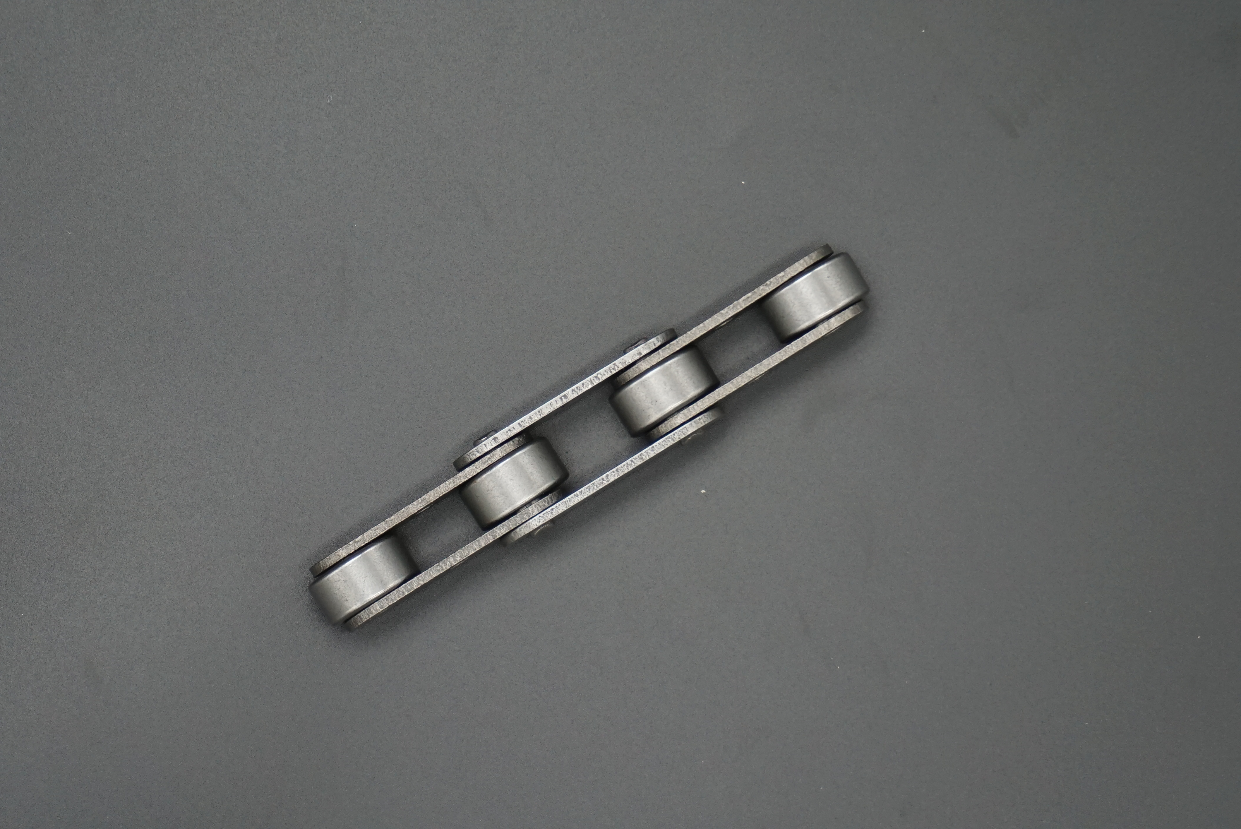
The Fracture Surface Speaks First
The break point is the most honest part of a failed chain. Before blaming the supplier, photograph the fracture at low and high magnification and classify it against four signatures, because the surface morphology alone often settles the question of who is responsible.
Fatigue Fracture
Fatigue failure shows a progressive, beach-mark or clamshell pattern radiating from a nucleation site, usually at the plate edge or the pin hole. The surface has a smooth, burnished region where the two crack faces rubbed together during growth, ending in a rough final-break zone where the remaining section tore apart. This signature means the chain ran for a long time under cyclic load below the ultimate tensile strength. The root cause is almost always repeated bending stress at the pin joint amplified by wear, misalignment or an incorrect lubrication film. A fatigue fracture is the classic fingerprint of a chain that was asked to do its job for too long under imperfect conditions.
Tensile Overload
A tensile overload break is sudden and ductile. The plate tears with pronounced necking and a fibrous, dull surface, and the fracture plane is roughly perpendicular to the load direction. This appears when a single shock load exceeds the chain rating: a jam, a blocked conveyor, a seized bearing, or a startup against a locked rotor. There is no beach-mark history because the crack had no time to grow, which is why an overload break is unambiguous evidence of an event rather than a process. The load record or the incident log is the verification step here.
Brittle Fracture
A brittle fracture is flat, granular and bright, often with chevron marks pointing back to the origin of the crack. It propagates with almost no plastic deformation. In roller chain this points to low-temperature operation, a hardened-and-brittle plate from over-tempering, or an internal material defect such as a non-metallic inclusion at the surface. It separates cleanly from fatigue because there is no slow-growth zone, and it separates from overload because the surface shows no necking. Hardness testing and a metallurgical section at the origin are the confirmation.
Hydrogen Embrittlement
Hydrogen embrittlement produces fine, intergranular cracks with a flat, sometimes flaky surface, frequently near plated or coated components. It results from acid pickling, electroplating without proper bake-out, or service in a hydrogen-rich environment. The tell is that a seemingly new, correctly rated chain snaps under modest static load with little warning. delayed fracture after plating is the classic red flag that points to a process fault rather than an operating fault, and it shifts responsibility firmly back to the manufacturing sequence rather than the user.
Pin and Bushing Wear: The Elongation Story
Elongation is the single most measured chain failure mode, yet it is the most misunderstood. A chain does not stretch like a rubber band; the pins and bushings wear at their contact, increasing the effective pitch of the assembly while every individual component keeps its own dimensions.
Elongation Mechanics
Wear at the pin-bushing articulation enlarges the joint clearance, so a measured multi-pitch span grows even though each part is geometrically intact. The elongation percentage is calculated against the nominal pitch:
Elongation % = ((Measured span minus Nominal span) divided by Nominal span) multiplied by 100.
For a 10-pitch section of a 1 inch (25.4 mm) pitch chain, the nominal span is 10 multiplied by 25.4 = 254 mm. If the measured span is 259 mm, elongation is ((259 minus 254) divided by 254) multiplied by 100 = 1.97%. Most drive standards call for replacement at 1.5% to 3% depending on the application, so the remedy is a measured decision, not a guess based on appearance. Record the exact span length and the number of pitches measured so the calculation is repeatable.
Lubricant Starvation
Without a separating film, the pin and bushing run in boundary contact, generating heat and a rapid polishing wear that quickly drives elongation past the limit. The inner faces show a bright, mirror-like burnish with little debris, because metal is being removed as fine particles and carried away by whatever oil remains. The verification step is the lubricant history: how often was the drive greased, and did the film actually reach the joint? A starvation failure is an operating-and-maintenance issue.
Abrasive Paste in Dusty Plants
In cement, aggregate, grain and mining plants, airborne dust mixes with residual lubricant to form a grinding paste. The wear faces look matte grey and heavily scored, and elongation accelerates by an order of magnitude compared with clean duty. This is contaminant-driven wear and is an environment-and-maintenance issue, not a manufacturing defect. The remedy is sealing, more frequent lubricant change, and covers, not a different supplier.
Normal Wear-Out Versus Premature Wear
Normal wear-out shows uniform, even polishing across all joints and a gradual elongation curve over the expected life, consistent with the application rating. Premature wear shows localized severe scoring, rapid elongation within weeks, and often a single badly worn section. The distinction matters for any claim: uniform wear supports the supplier’s specification; localized premature wear supports the user’s operating conditions or a mixed old-and-new installation. Compare the elongation rate against the rated life to separate the two.
Plate Cracking at the Pin Hole
Plates most often crack at the hole that carries the pin, because that is where the stress concentrates under tension and where residual stresses from assembly live.
Press-Fit Stress and Interference Fit
The pin is pressed into the plate with an interference fit that must hold the joint rigid without overstressing the plate. Too tight a fit induces residual hoop tension around the hole; too loose a fit lets the pin rotate in the plate, fretting the bore. Both shorten fatigue life. The correct interference is a function of plate thickness and pin diameter and is fixed by the manufacturer’s drawing, so a cracked plate with low elongation is a fit question before it is a material question.
Hole Quality and Shot Peening
A drilled or punched hole with a burr, a taper, or a rough surface finish becomes a crack origin. Shot peening introduces a compressive surface layer that resists fatigue cracking, so a plate that was under-peened or un-peened cracks earlier than specification. Inspect the bore edge under magnification: a clean, rounded, peened edge is evidence of good process control; a sharp, torn edge is evidence of a process fault. The fracture origin location relative to the bore is the confirmation.
Wrong Interference Shortening Fatigue Life
When a chain is assembled with a pressed pin that was not matched to the plate bore tolerance, the residual stress at the hole can cut fatigue life by a large factor. A fatigue crack originating exactly at the bore edge, on a chain with otherwise low elongation, is the signature of an interference-fit problem rather than an operating overload. The verification is to measure the actual bore diameter and pin diameter and compare against the drawing.
Roller and Bushing Spalling in Conveyor Duty
Conveyor chains see a different stress than transmission chains: they carry load continuously and often absorb direct impacts from the product they move.
Impact Loading From Drop Height
When product drops onto a conveyor from height, each roller receives a repeated impact that flakes the hardened surface of the roller or bushing. Spalling appears as shallow craters and loose chips on the load face. Reducing drop height or adding cushioning is the operating remedy; insufficient hardened depth or a soft case is the manufacturing question to check with a micro-hardness traverse across the section.
Misalignment and Sprocket Tooth Wear Interaction
A misaligned conveyor forces rollers to enter sprocket teeth at an angle, producing edge loading that chips the roller and accelerates spalling. Worn sprocket teeth then present a poor seating surface, so the two faults compound. The worn tooth profile and the chipped roller should be assessed together, not in isolation, because condemning one without the other simply repeats the failure on the next component.
The Sprocket Is a Co-Suspect
Chains and sprockets wear as a pair. A failure attributed to the chain is frequently shared with, or caused by, the sprocket.
Worn Tooth Profile Accelerating Chain Wear
A sprocket with hooked or pointed teeth changes the contact geometry, increasing pressure on the roller and bushing and accelerating elongation. Replacing the chain alone on a worn sprocket simply transfers the wear to the new chain at the same accelerated rate, which is why the new chain then fails quickly and the user wrongly blames the supplier a second time.
Mismatch Between New Chain and Worn Sprockets
New chain pitch is tight; a worn sprocket has effectively enlarged tooth spacing. The mismatch produces a binding or climbing action at engagement, causing noise, impact and rapid joint wear. Measure the sprocket pitch circle and compare it against the new chain pitch before condemning the chain, because a measurable pitch difference is the evidence that the sprocket, not the chain, was due for replacement.
The Correct Replacement Sequence
Replace the chain and sprocket as a set when wear is advanced, or at minimum replace sprockets when a new chain is fitted to a drive that has already worn one chain to its limit. Document the sprocket condition in the evidence pack so the root cause is unambiguous, and specify matched sets from the start for failure-sensitive lines where downtime is expensive.
Installation and Alignment Faults That Masquerade as Defects
Many so-called manufacturing defects are actually installation errors that only become visible after failure, when the chain has already been condemned by the user.
Shaft Parallelism and Misalignment
Shafts that are not parallel load one side of the chain, producing uneven plate wear and one-sided roller spalling. Angular misalignment rotates the chain off the sprocket plane; offset misalignment shifts the pitch lines. All three are set with a straightedge and feeler gauges at installation, not discovered after breakdown. The verification is to re-measure shaft alignment on the failed drive and compare it to the drawing tolerance.
Centre Distance, Sag and Tension Setting
Excessive centre distance with too little tension lets the slack strand sag and whip, hammering the joints. Too much tension overloads the bearing and the pins. Set tension by the drive’s specified deflection per unit span, measured with a spring scale or a deflection gauge, rather than by feel. specified chain deflection is the only defensible tension target, and recording the measured deflection turns a dispute about “too tight” into a numerical fact.
Lubrication and Environment Failures
The lubricant is part of the machine. The wrong choice or the wrong environment produces failures that look like material defects but are actually specification mismatches.
Wrong Lubricant Grade
A too-viscous oil will not penetrate the tight joint; a too-thin oil will not hold the film under load. Both starve the articulation and accelerate wear. Match the grade to speed, load and temperature per the drive specification, and keep the application record so the grade can be verified against the failure mode that appeared.
Over-Lubrication Attracting Abrasive Dust
A heavily greased exterior in a dusty plant becomes a dust magnet, packing abrasive paste into the joint and onto the roller. More lubricant is not always better; the correct amount is what reaches the articulation and does not pool externally where it collects contaminants. The tell is a thick external crust with a clean-but-scored internal face.
Washdown Chemical Attack and Food-Grade Requirements
In food and beverage lines, frequent high-pressure washdown with caustic or acidic cleaners attacks standard chains and seals. Food-grade duty requires NSF H1 lubricants and corrosion-resistant finishes. A chain that rusts through after washdown failed an environment specification, not a strength specification. NSF H1 rated lubrication is the documented requirement for any claim in food service, and the washdown chemistry record is the verification step.
Building the Evidence Pack for a Warranty Claim
A claim succeeds only when the evidence is repeatable and complete. The buyer should assemble the following before contacting the supplier, because a partial pack invites a partial answer.
Photographs With Scale
Shoot the fracture, the worn joints and the sprocket teeth with a ruler or calibration card in frame, at both overview and macro distance. Un-scaled photos are not evidence, because they give no sense of wear depth or crack size, and they cannot be compared against a replacement unit later.
Chain Length and Pitch Measurements
Measure a clean 10- or 20-pitch span against nominal pitch and record the elongation percentage using the formula above. Mark the exact location of the measurement on the chain and state the number of pitches measured, so the supplier can reproduce the number exactly.
Running Hours, Load Records and Lubricant History
Provide operating hours, the peak and average loads from the drive log, the lubricant grade and the re-grease interval. These establish whether the chain was used inside its rating, which is the central question in any responsibility dispute.
Sprocket Condition and a Repeatable Measurement Protocol
Record sprocket tooth wear, replacement dates and alignment checks. The buyer can repeat the same measurements on the replacement unit, which turns a dispute into a controlled comparison and removes opinion from the discussion.
Diagnostic Table: Symptom to Remedy
Beach-marked plate fracture
- Likely cause: fatigue from cyclic load with wear, misalignment or poor lubrication.
- Verification step: photograph fracture at magnification; confirm elongation and lubrication history.
- Remedy: correct alignment, improve lubrication, replace at the elongation limit.
Flat bright brittle break
- Likely cause: brittle fracture from low temperature, over-tempering or material defect.
- Verification step: check service temperature and hardness; review heat-treatment record.
- Remedy: specify correct material and temper; control operating temperature.
Rapid elongation in dusty duty
- Likely cause: abrasive paste from contaminant-laden lubrication.
- Verification step: measure elongation rate; inspect joint faces for matte scoring.
- Remedy: seal the drive, change lubricant more often, fit guards and covers.
Chipped rollers on conveyor
- Likely cause: impact loading or misalignment with worn sprocket teeth.
- Verification step: measure drop height and sprocket tooth profile; check alignment.
- Remedy: reduce drop height, replace sprocket set, correct alignment.
One-sided plate wear
- Likely cause: shaft non-parallelism or offset misalignment.
- Verification step: check shaft parallelism with straightedge and feeler gauge.
- Remedy: re-align shafts to specification; re-set tension by deflection.
Rust after washdown
- Likely cause: chemical attack on a non-food-grade or unprotected chain.
- Verification step: confirm washdown chemistry and chain finish.
- Remedy: specify NSF H1 lubricant and corrosion-resistant coating.
Frequently Asked Questions
How do I tell fatigue from a simple overload break?
Fatigue shows a slow-growth beach-mark zone and a small final-break area, proving long cyclic service below the rating. A tensile overload breaks with necking and a fibrous surface and no growth history, proving a single excessive load event rather than wear over time.
What elongation percentage means the chain must be replaced?
Calculate elongation percent from the measured span against nominal pitch. Replace at the limit set by the drive, commonly 1.5% to 3%, because beyond that the chain climbs worn sprocket teeth and damages the sprockets as well as itself.
Can a new chain fail on an old sprocket?
Yes. A worn sprocket has enlarged effective tooth spacing that mismatches new chain pitch, causing binding and accelerated joint wear. Always assess sprocket condition and pitch before fitting a replacement chain, and replace the sprocket set when wear is advanced.
Does over-lubrication help in a dusty plant?
No. Excess external grease collects abrasive dust into a grinding paste at the joint and on the roller. The correct amount is what penetrates the articulation without pooling on the exterior surface where it attracts contaminants.
What evidence should I send with a warranty claim?
Send scaled macro and overview shots of the fracture, worn joints and sprocket teeth, plus the measured elongation, running hours, load and lubricant records. Unscaled photos alone are not sufficient evidence, and a missing lubricant history weakens any manufacturing claim.
Related Pages
- Key Factors Influencing Roller Chain Prices
- Maintenance Cost Comparison of Roller Chains and Chain Drives
- Selection of Standard and Non-Standard Roller Chains
- The Lifespan Advantage of Roller Chains vs Belt Drives
Tip: Always photograph the fracture with a scale before removing the chain from the machine, because the installed geometry is itself evidence of alignment and tension faults that no bench inspection can recover.
Post time: Oct-26-2026