Roller Chain Drive Design in Textile Machinery
In the continuous and high-speed operation system of textile machinery, roller chain drives play a core role in power transmission, speed matching, and station synchronization. Their design rationality directly determines the equipment’s operational stability, yarn quality consistency, and overall machine lifespan. This article, aimed at international textile equipment manufacturers, machine design engineers, and overseas buyers, systematically elaborates on the complete design logic of roller chain drives in textile machinery from the dimensions of working condition adaptation, parameter design, selection specifications, lubrication, and maintenance, helping to achieve the transmission goals of low vibration, low noise, and long-term maintenance-free operation.
I. Typical Working Conditions and Design Constraints of Roller Chain Drives in Textile Machinery
Textile machinery operating conditions are characterized by continuous heavy loads, high-speed operation, high dust and lint, temperature and humidity fluctuations, and frequent start-stop cycles, imposing stringent constraints on roller chain drives:
Speed Characteristics: Units such as carding, drawing, roving, and winding are mostly medium-to-high-speed drives, with chain speeds typically ranging from 0.5 to 8 m/s, requiring high stability, weak polygonal effects, and low impact.
Load characteristics: Continuous operation + frequent starts and stops + instantaneous impacts require sufficient tensile strength, fatigue strength, and wear resistance.
Environmental characteristics: Flakes, cotton dust, and fiber debris easily penetrate the hinges, accelerating wear; some humid and hot workshops require rust and corrosion resistance.
Precision requirements: High synchronization is required for drawing, winding, and twisting stations; transmission errors directly affect yarn uniformity and breakage rate.
Spatial constraints: Compact frames, dense shaft systems, and limited center distances often necessitate small pitches, multiple chain rows, and compact layouts.
II. Core Design Process of Roller Chain Drive (Textile Machinery Specific)
1. Define Design Input Conditions
Transmitted Power P (kW), Driven/Driven Shaft Speed n₁/n₂ (r/min)
Transmission Ratio i, Center Distance Range, Installation Space and Shaft Layout
Load Characteristics, Continuous Operating Time, Ambient Temperature, Humidity, and Dust Conditions
Life Target, Lubrication Conditions, Maintenance Cycle Requirements
2. Optimize Transmission Ratio and Sprocket Tooth Count
Transmission Ratio i: Commonly used in textile machinery, i = 2–5, preferably ≤ 3.5, to avoid insufficient wrap angle, tooth skipping, and uneven load distribution caused by a large transmission ratio.
Small Sprocket Tooth Count z₁:
General Operating Conditions: z₁ ≥ 17
High-Speed/Impact Operating Conditions: z₁ ≥ 21–25, reducing impact, minimizing polygonal effects, and improving stability.
Large Sprocket Tooth Count z₂: Recommended z₂ ≤ 100–120, excessive tooth count can easily lead to chain skipping or derailment due to wear and elongation.
The number of teeth should ideally be odd, coprime to the number of chain links (even), resulting in more even wear and extended lifespan.
3. Chain Pitch and Row Selection (Core Points of Textile Machinery)
Pitch is a key parameter determining load capacity, stability, noise, and size:
Principle: Prioritize small-pitch single-row chains when sufficient load capacity is required; select small-pitch multi-row chains for high-speed, heavy-load applications.
Common Matchings:
Light Load High Speed (Winding, Grooving): 06B, 06C, 08A Small-Pitch Precision Roller Chains
Medium Load Medium High Speed (Drawing, Roving): 08A, 08B, 10A Single/Double-Row Chains
Heavy Load Continuous (Cardging, Sizing, Weaving Warp Feed): 10A, 12A, 16A Double/Triple-Row Chains
Small center distance, large transmission ratio, limited space: Small-pitch multi-row chains are the optimal solution.
4. Power Calculation and Chain Rated Power Verification
Power Calculation: Pca = KA × P
KA is the usage factor. Recommended values for textile machinery:
Continuous stable load: KA = 1.1–1.3
Slight impact / Frequent start-stop: KA = 1.3–1.5
Heavy load impact / Multi-unit linkage: KA = 1.5–1.7
Based on Pca and the small sprocket speed n₁, select the chain number and number of rows from the rated power curve, ensuring the rated power ≥ Pca.
5. Chain Link Count, Center Distance, and Wrap Angle Control
Number of Chain Links: Preferably even numbers to avoid weakening strength and stress concentration caused by excessive chain links.
Center Distance: Commonly a = (30–50)p; if space is limited, not less than a ≥ 20p to ensure wrap angle and meshing stability.
Small sprocket wrap angle: ≥ 120°; if the transmission ratio is large or the center distance is small, use a tensioning device to compensate for insufficient wrap angle.
6. Chain Speed Verification and Lubrication Method Matching
Chain Speed v: Textile machinery primarily uses low to medium speeds (v≤6 m/s), while high-speed sections require enhanced lubrication and dynamic balancing.
Lubrication methods are categorized by chain speed:
v≤1 m/s: Manual periodic lubrication
1–3 m/s: Drip lubrication/oil bath lubrication
3–6 m/s: Splash lubrication/oil pump pressure circulation lubrication
v>6 m/s: Forced cooling + pressure lubrication to reduce temperature rise and wear.
7. Shaft Force and Safety Factor Verification
Effective circumferential force: F=1000P/v
Shaft force: FQ=KQ×F, KQ is taken as 1.15–1.2 (stable load) or 1.2–1.3 (impact load)
Safety factor: Static strength ≥4–5, fatigue strength ≥2–2.5, meeting continuous operating life requirements.
III. Reference for Roller Chain Drive Configurations in Typical Textile Machinery Models
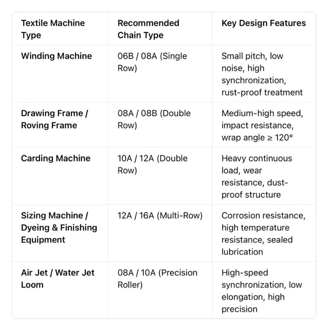
IV. Materials, Structure, and Processes: Enhancing Adaptability to Textile Working Conditions
Materials and Heat Treatment: Chain plates, pins, and bushings are made of high-quality alloy steel, undergoing precise heat treatment to improve fatigue strength and wear resistance.
For humid/corrosive environments, stainless steel roller chains are preferred, balancing strength and rust prevention.
Structural Optimization: Precise fit tolerances reduce clearance and impact, minimizing polygonal effects and noise.
A full roller structure is preferred to reduce friction with sprocket teeth, improving wear resistance and stability.
Multi-row chains employ a precise alignment structure for even load distribution, preventing off-center load failure.
Surface Treatment:
Standard operating conditions: Phosphating + rust-preventive oil
Humid/dusty conditions: Blackening, zinc plating, nickel-phosphorus coating
Food-grade/High-end textiles: Stainless steel material, meeting cleaning and corrosion prevention requirements.
V. Installation, Tensioning, and Maintenance: Ensuring Long-Term Stable Operation
Installation Points: Both shafts must be strictly parallel, and the sprockets must be precisely aligned. Excessive deviation can cause uneven wear, chain skipping, and abnormal noise.
Chain sag is moderate: When the center distance is ‘a’, the sag f = (0.01–0.02)a.
Tensioning Design: When the center distance is not adjustable, configure a tension wheel/tension plate, placed inside the slack side, to ensure stable tension.
Maintenance Strategy: Regularly clean fly ash and dust to prevent hinge jamming.
Select textile-specific chain oil according to the working conditions to ensure penetration and long-term lubrication.
Monitor elongation; replace promptly if it exceeds 2%–3% to avoid affecting transmission accuracy and yarn quality.
VI. Design Summary: The Golden Rules of Roller Chain Drives in Textile Machinery
Working Condition Priority: Matching continuous heavy loads, high speeds, dusty environments, and temperature variations in textile production.
Optimal Parameters: Small pitch, reasonable number of teeth, even number of links, sufficient wrap angle, and precise centering.
Selection and Adaptation: Select small-pitch precision chains for light loads and high speeds; use multi-row chains for heavy loads; use stainless steel chains for corrosion protection.
Proper Lubrication: Lubrication methods are matched to chain speed to extend lifespan and reduce noise and breakage rates.
Standardized Maintenance: Regular cleaning, tension checks, and wear monitoring ensure long-term stable operation.
For global textile equipment manufacturers and overseas procurement partners, stable and reliable roller chain drives are a key foundation for enhancing the core competitiveness of equipment. Following the above design logic effectively achieves the transmission goals of low vibration, low noise, high precision, and long lifespan, providing a stable, efficient, and sustainable power transmission solution for high-end textile machinery.
Post time: Mar-20-2026