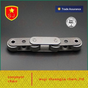
SolidWorks is a powerful computer-aided design (CAD) software widely used in various industries. It allows engineers and designers to create realistic 3D models and simulate the performance of mechanical systems. In this blog, we’ll take a deep dive into the process of simulating roller chains using SolidWorks, giving you step-by-step instructions to achieve accurate and reliable results.
Step 1: Gather the necessary data
Before starting to use SolidWorks, it is important to understand the necessary parameters and specifications of roller chains. These may include chain pitch, sprocket size, number of teeth, roller diameter, roller width, and even material properties. Having this information ready will help create accurate models and efficient simulations.
Step 2: Model Creation
Open SolidWorks and create a new assembly document. Start by designing a single roller link, including all appropriate dimensions. Accurately model individual components with sketches, extrusions, and fillets. Make sure to include not only the rollers, inner links and pins, but also the outer links and connecting plates.
Step 3: Assemble the Chain
Next, use the Mate function to assemble the individual roller links into a complete roller chain. SolidWorks provides a range of mate options such as coincident, concentric, distance and angle for precise positioning and motion simulation. Make sure to align the roller links with the defined chain pitch to ensure an accurate representation of the real life chain.
Step 4: Define Material Properties
Once the chain is fully assembled, material properties are assigned to the individual components. SolidWorks provides several predefined materials, but specific properties can be manually defined if desired. Accurate material selection is very important as it directly affects the performance and behavior of the roller chain during the simulation.
Step 5: Applied Motion Research
To simulate the motion of a roller chain, create a motion study in SolidWorks. Define the desired input, such as the rotation of a sprocket, by applying a motion motor or rotary actuator. Adjust speed and direction as needed, keeping operating conditions in mind.
Step 6: Analyze the Results
After performing a motion study, SolidWorks will provide a comprehensive analysis of the behavior of the roller chain. Key parameters to focus on include chain tension, stress distribution and potential interference. Analyzing these results will help identify potential issues such as premature wear, excessive stress, or misalignment, guiding you to necessary design improvements.
Simulating roller chains with SolidWorks enables engineers and designers to fine-tune their designs, optimize performance, and identify potential issues before moving to the physical prototyping stage. By following the step-by-step process outlined in this blog, mastering the simulation of roller chains in SolidWorks can become an efficient and effective part of your design workflow. So start exploring the potential of this powerful software and unlock new possibilities in mechanical design.
Post time: Jul-29-2023

