Designing mechanical systems often involves the integration of multiple components to ensure smooth operation. Roller chains are one such component widely used in power transmission systems. In this blog, we will guide you through the process of adding a roller chain in SolidWorks, a powerful CAD software widely used in the industry.
Step 1: Create a New Assembly
Start SolidWorks and create a new assembly document. Assembly files allow you to combine individual parts to create complete mechanical systems.
Step 2: Select Roller Chain Components
With the assembly file open, navigate to the Design Library tab and expand the Toolbox folder. Inside the toolbox you will find various components grouped by function. Find the Power Transmission folder and select the Roller Chain component.
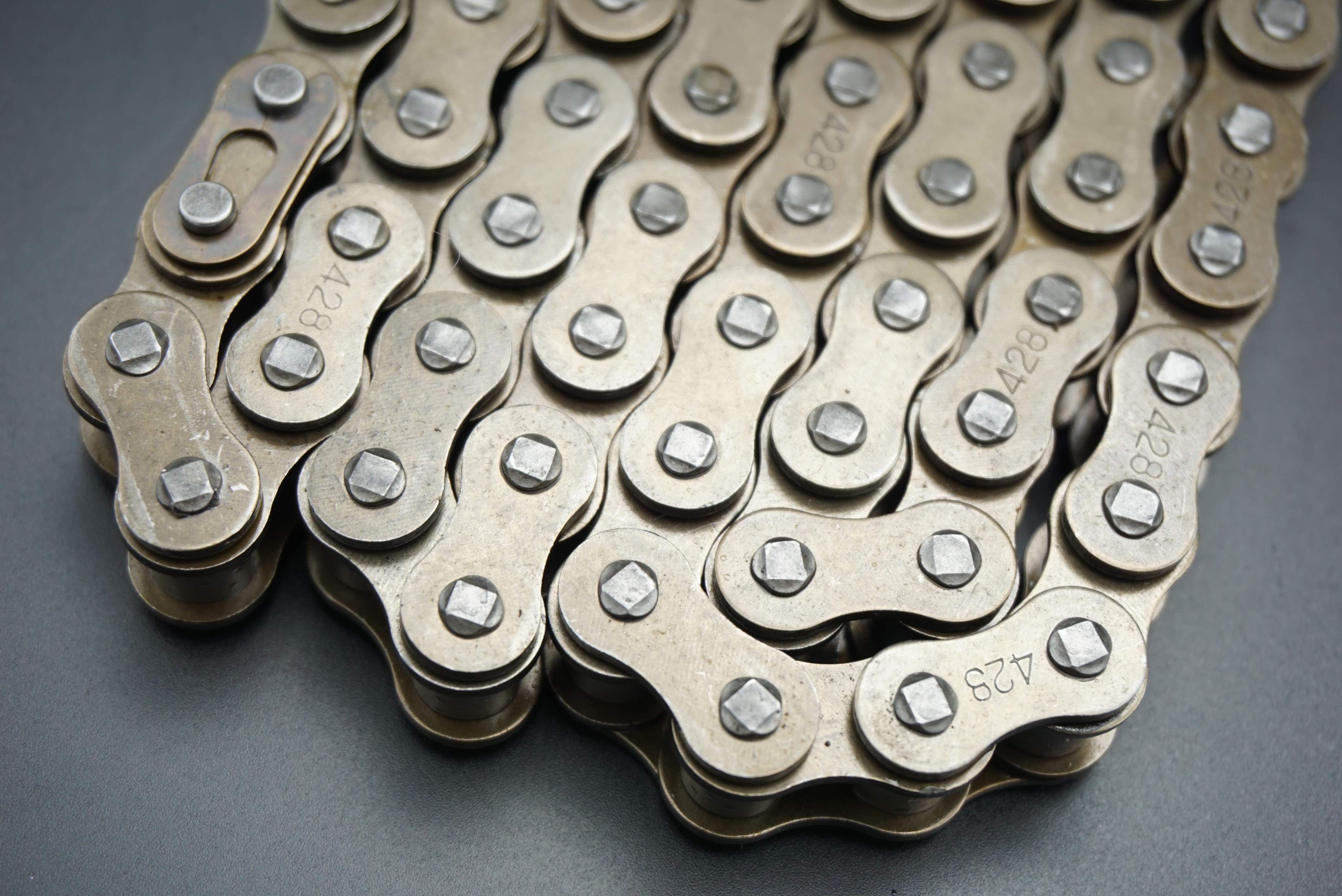
Step 3: Put the Roller Chain Into the Assembly
With the roller chain component selected, drag and drop it into the assembly workspace. You’ll notice that a roller chain is represented by a series of individual links and pins.
Step 4: Define the chain length
To determine the right chain length for your specific application, measure the distance between the sprockets or pulleys where the chain wraps. Once the desired length is determined, right click on the chain assembly and select Edit to access the Roller Chain PropertyManager.
Step 5: Adjust Chain Length
In the Roller Chain PropertyManager, locate the Chain Length parameter and enter the desired value.
Step 6: Select Chain Configuration
In the Roller Chain PropertyManager, you can select various configurations of roller chains. These configurations include different pitches, roll diameters and sheet thicknesses. Choose the configuration that best suits your application.
Step 7: Specify Chain Type and Size
In the same PropertyManager, you can specify the chain type (such as ANSI Standard or British Standard) and the desired size (such as #40 or #60). Make sure to choose the proper chain size based on your project requirements.
Step 8: Apply Chain Movement
To simulate the motion of the roller chain, go to the Assembly toolbar and click the Motion Study tab. From there, you can create mate references and define the desired motion of the sprockets or pulleys that drive the chain.
Step 9: Complete the Roller Chain Design
To ensure a complete functional design, inspect all components of the assembly to verify proper fit, clearance and interaction. Make the necessary adjustments to fine-tune the design.
By following these simple steps, you can easily add roller chain to your mechanical system design using SolidWorks. This powerful CAD software simplifies the process and enables you to create accurate and realistic models. Utilizing the extensive capabilities of SolidWorks, designers and engineers can finally optimize their roller chain designs for improved performance and efficiency in power transmission applications.
Post time: Jul-15-2023